A blog with tips, tricks and tutorials to help you prepare your CCIE Wireless lab exam.

Thursday, December 17, 2009

WPA/WPA2 broadcast key rotation on a controller

This one is (IMHO) way beyond what you should need to remember for the exam, but I actually dreamed about it last night, so I though I should share the fun!
Special dedication to Kyle, he is the one who raised this issue and found the solution.... :-)
So here is the deal: when you use WPA or WPA2, your wireless client gets 2 keys: one unicast key, for its own traffic to and from the AP, and one broadcast key, which is a common key for all clients in the same cell. This broadcast key is used when the AP sends broadcast messages to all clients in the cell, so it's a shared key.
You may want to rotate those keys, change them every now and then so that a wannabee hacker would not have enough packets using a specific key to even dream of running an attack against your encryption scheme.
Changing the unicast key can be done by setting the EAP session, everytime the session is renewed, so is the unicast key... but the broadcast key is not, because it is shared. On the autonomous APs, you can rotate the broadcast keys from the Security > Encryption Manager page:


You can enable rotation at regular intervals. The gotcha here is that only 802.1X clients can join a network that has this feature enabled.
When using WPA, you can also enable key rotation "on membership termination" (every time a client leaves the cell, the key is rotated for the clients still in the cell), or on "membership capability change" (everytime a client using static WEP enters or leaves the cell, the key is rotated).

Ok, but what about the controllers? How to rotate the broadcast key on the WLC? There is no checkbox, and no CLI command for that... the key is rotated every hour... what? I want this feature for my clients security!!
Kyle found this nice info:
CSCsi27596—The controller lacks a supported way to configure the broadcast key rotation interval. Instead, it is hardcoded to a group key rotation interval of 3600 seconds (1 hour).
Workaround: On the console, configure the hidden command devshell dot1xUpdateBroadcastRekeyTimer(seconds). This command does not work in an SSH or Telnet session and does not survive a reboot.
Example:
(Cisco Controller) >devshell dot1xUpdateBroadcastRekeyTimer(86400)
value = 0 = 0x0
I dreamed of it because the example, instead of rotating the key every hour, seems to rotates it every... day (unless 8600 is the max value)! Wow, nice and a lot more secure!

I hope you don't need that for the lab, because this is pushing the system to its limit (and I hope you won't dream of it), but it is fun to know (or at least to know where to find it)...
:-)

Friday, December 11, 2009

WLC Layer 2 and Layer 3 Security Policies

In the Wireless Guest WLAN scenario, you need to create a WLAN on the foreign controller, and the same WLAN on the Anchor controller. You then add each controller to the other controller's mobility list (good practices dictate that controllers should be in DIFFERENT mobility groups. So they know each other, but they do not belong to the same mobility group). Last step, you define the Anchor as the Mobility Anchor for this WLAN on both the Foreign and the Anchor controller (don't forget to define the Anchor as the Mobility Anchor on the Anchor itself! This controller needs to know that it is one end of a EoIP tunnel).


That's the easy part, you can find tutorials on this config almost everywhere, for example at:
http://www.cisco.com/en/US/docs/wireless/controller/4.2/configuration/guide/c42mobil.html

Now, two questions:
1. Can you combine Layer 3 security (Web Authentication) with Layer 2 security?
2. What exactly needs to be the same and what can be different on the WLAN configuration on both controllers?

1. Yes! And you'd better do it if you want to secure the wireless part. With standard Layer 3 policy only, the only moment that is protected is when you access the Web authentication page and enter your credentials: at that time, you use HTTPS, so you are safe. As soon as authentication is complete, you use the pure Open WLAN, no encryption no encryption. Anybody sitting next to you can eavesdrop what you send and receive with no restriction... haven't you try already when waiting for your flight in an Airport lounge? Well, don't, it is completely in clear and fun to watch, but watching is completely forbidden in most countries...
So you can protect the traffic between the wireless client and the AP by adding to the Layer 3 policy a Layer 2 policy... but not in any conditions. For example, if you try to add WPA/802.1X and click Apply, you get this:


Well, we expected that! If you think about it, 802.1X is a user authentication that occurs at Layer 2... if this worked, you would have to start an 802.11 authentication/association process, get authenticated at Layer 2 with a strong mechanism (PEAP, FAST or even EAP-TLS!), then have to re-authenticate at Layer 3... not very handy and not very logical (why do you need this Layer 3 authentication if we already know who you are?)... and single sign on is out of reach for now...
So you can add a Layer 2 protection mechanism, but it has to be ENCRYPTION, not AUTHENTICATION. In other words, you can use WEP, WPA or WPA2, provided that you rely on PSK, not 802.1X. And then it works. This is how it looks:


Details of Layer 2 page:

And Layer 3 page:

Not very practical for public networks, as you would have to distribute the PSK to your Wireless LAN guest users, but fun as a configuration challenge.

2. Everything on the WLAN has to be strictly identical on the Foreign controller and on the Anchor controller, except:
- the Interface: you can send your users to a DMZ dynamic interface on the Anchor controller to the Management Interface on the Foreign controller (it is actually going to be the Management interface whatever your configured interface is on the Foreign controller, as Controller to controller communication always use the Management interface), so this can be different, and the Foreign controller does NOT need to (and should not) be configured with the DMZ dynamic interface you create on the Anchor.
- RADIUS server: in the WLAN Security > AAA Servers tab, you Anchor controller can define specific RADIUS server(s) to use, which your Foreign controller does not care about. Authentication is done on the Anchor, not on the Foreign, so you can call RADIUS servers on the Anchor and not on the Foreign, no problem. This can also be one difference.
- Profile Name: when you configure the WLAN, you setup a Profile Name and an SSID. The Profile name is a local identifier and not exchanged between controllers, so it can be different on the Foreign and the Anchor.
- Encryption key! Yep, that one is funny. One of my friends (thanks Amir!) discovered that 2 weeks ago. If you add Layer 2 policy with WEP, WPA or WPA2, you need to define a PSK... the PSK can be different on the Foreign and the Anchor! Now... which one will be used by the client? The one on the Foreign! Yes, this is the exception, everything comes from the Anchor controller, except this key. When you think about it, this makes logical sense. Your Layer 2 connection is to an access point connecting to the Foreign Controller, and you need to get to the Foreign controller before being sent through EoIP to the Anchor. So the Layer 2 protection is between you and the AP (connecting to the Foreign). It is therefore very logical to think that the key you need on the client is the key that the Foreign controller sends to the foreign AP!
Notice that you MUST define a key on the Anchor if you define a key on the Foreign: in the mobility exchange, they do tell each other that there is a Layer 2 key, and of which type (WEP, WPA or WPA2). It is just that they do not actually send that key, so it can be different on both controllers...
Wireless is so much fun!

Non-routed WLAN

You probably know the standard Guest WLAN scenario, with an anchor controller. You find it in most WLC configuration guides since code 3.2.


In this scenario, the wireless user is using a Web Auth WLAN and associates to an access point connected to the Foreign Controller. As you configure a Mobility Anchor on both the Foreign and the Anchor for the Web Auth WLAN, the wireless user is sent to the Anchor controller, gets its IP address from there, and starts its IP journey from the Anchor. In this classical scenario, the wireless user is limited to Internet access: the wireless laptop gets an IP address in the DMZ scope (10.10.10.0/24 in this example), from a DHCP somewhere in the DMZ. The Firewall is its gateway, and only allows traffic to the Internet, forbidding traffic back to the internal network.

Fine. But what if the network design is like this?

In this design, your firewall is integrated  into your edge router, and the "DMZ" just relies on subnets on the main switch.
In this configuration, your mission, if you accept it, is to design a non-routed WLAN... what is that? A config that will prevent the wireless user, sent to the Anchor controller, from getting to your corporate network... no ACLs allowed on the main switch...
This is how it works. You still create the same WLAN on the Foreign controller and on the DMZ controller, put them on the same mobility list (but in different mobility groups!), and set the Anchor as the Anchor controller.
What is different here is the IP assignment. Your must configure your main switch only with Layer 2 awareness of the DMZ VLAN. So if DMZ is network 10.10.10.0/24, VLAN 10, create VLAN 10 on the main switch, but not the Layer 3 SVI interface. As the main switch does not know subnet 10.10.10.0/24, it cannot route this subnet. The link from the main switch to the corporate network, configured as trunk, would allow all VLANs except vlan 10. For example:
conf t
vlan 10
interface g3/1
description --- to internal network
switchport trunk encapsulation dot1q
switchport mode trunk
switchport trunk allowed vlan except 10
Perfect. Now how does this wireless client get an IP address? The easiest way in this simple scenario (you saw that we even removed the DHCP server from the DMZ) is to provide the IP address from the DMZ controller. This implies 3 elements:
1. When you create the interface associated to the WLAN on the Anchor controller, the DHCP server IP address is the Anchor Controller Management IP address, like this:


The DMZ controller obviously has an IP address it this subnet. So, again, the DHCP server IP address is the controller Management Interface IP address (not the VLAN 10 controller dynamic interface IP address).

2. The gateway is the edge router, that is supposed to have an IP address in this DMZ subnet (10.10.10.254 in this example).

3. Create a DHCP scope on the Anchor controller for this 10.10.10.0/24 subnet.

This is it!

Wednesday, December 9, 2009

Written questions for the CCIE Wireless lab

"Effective January 4, 2010, the CCIE. Service Provider, Storage, and Wireless
Lab Exams will add a new type of question format in a section called Core
Knowledge. In this new section, candidates will be asked a series of four
open-ended questions which require a short written response be entered into
the computer--typically several words. The questions will be randomly drawn
from a pool of questions on topics eligible for testing. Candidates can
review the topics by visiting the CCIE track information on Cisco.com or
Cisco Learning Network. No new topics are being added as a result of this
change. Candidates will have up to 30 minutes to complete the Core Knowledge
section and may not return to it once they have moved on. A passing score on
the Core Knowledge section is required to achieve certification. Core
Knowledge questions were implemented on Routing and Switching labs in
February 2009, Security labs in June 2009, and Voice labs in July 2009, and
allow Cisco to maintain strong exam security and ensure only qualified
candidates are awarded CCIE certification. Candidates with exam dates
January 4, 2010 or later should expect to see the new question format on
their lab exam."

The aim of these 4 questions is to ensure that when you take the lab, you really know your stuff (Wireless in this case of course), and did more than just learn by heart series of click to answer a specific configuration question... so you will be asked 4 questions about wireless, and will need to answer in the form a a short paragraph or a few words, showing that you know what this is about. Of course, NDA prevents from giving real questions (and I have NO information anyway about these questions, that are kept very secretly as you can guess), but they could be questions like "In Wireless > 802.11a >RRM >DCA page, what does the "Avoid Foreign AP Interference" feature achieve?"... You are given a box where you can type your answer freely. It can be something as short and simple as "detect neighbor APs and try to avoid their channels when changing our APs channels", to something a lot longer and detailed, it is up to you. You just need to show the proctor that you know what this is about and give a simple (but still clear and precise) explanation, you do not need to write a 50 page white paper on the feature.
You have 30 minutes to answer all 4 questions, which is more than enough. You NEED to have most of them right to pass. Basically, you can have one wrong. More than one wrong, and you fail on your lab, even if your lab config is perfect...

Friday, December 4, 2009

Mobility group / list / domain RF Group

At the beginning of the world, wireless networks were small: one controller and a few access points. Then, the young Airespace company (some of you may even remember the even older name, Blackstorm Network) started having larger clients, needing several controllers. Some of them wanted to have controllers isolated from one another, some others wanted a "cluster logic" between controllers, to create a larger virtual controller.
So the Airespace team created the Mobility Group concept, also called Mobility Domain (these two terms mean exactly the same thing). If two controllers belong to the same mobility group, they exchange information about clients (namely, when a new client connects to a controller, this controller informs the other controllers. The result is that when the client roams to another controller, the new controller knows if it is a "new" client (no controller reported this client before), or a roaming client (one controller in the group/domain reported this client before). If it is a roaming client, you can even know which controller the client is coming from, which is very handy to transmit the client credentials from one controller to the other. You could have 12, then later on 24 controllers in the same mobility group/domain.
To make two controllers members of the same mobility group, you needed two steps:
1. Input the same string in the Controller > General > Mobility Domain Name field, so that both controllers have the same mobility group/domain value.
2. Inform each controller about the other, in Controller > Mobility Management > Mobility group. Each controller needs to know the other controller's Management IP address and built-in MAC address.
As a side effect of roaming, we also used to say that if you want roaming to occur smoothly, you'd better run the same code on both controllers (so that they speak the exact same language), and also configure the same virtual gateway IP address (this address is used as a "virtual address" to make the client think that it connects to one big virtual controller instead of several physical controllers).

At that time life was simple... :-) Then some clients also asked to segregate RRM... this was their scenario (kind of): I have 3 controllers, 2 in my office building and one in my warehouse. I want roaming between all of them (okay, so same mobility group/domain and controllers know each other) BUT I do not want cooperation for RRM between the office building and the warehouse. Why? Basically because the warehouse is a specific environment, most of the time isolated from the office and it has specific settings, so I do not want a sort of global master of the network that would not be able to distinguish the warehouse environment from the office environment.
Fine! We are going to create another group concept, the RF-Group (defined in Controller > General). You can put one string for the office building controllers, and another string for the warehouse controller. IF the strings are different, the controllers won't work together for RRM management...
Ok, this is how it works: when you add controllers to the local Mobility group/domain, those controllers send an introduction message to each other (hey, I am X, and oh BTW, my RF-Group is Y). All members of the mobility group also having a common RF-Group value elect an RF-Group leader. The RF-Group leader decides of an RF-Group hash (that represents this RF-Group name shared by those controllers) and sends it back to all members of the RF-Group.
Then, each AP sends, every 60 seconds, a RRM neighbor message from its radios, on all serviced channels. This message contains, among other things, the RF-Group hash. Neighboring APs hearing this message forward it to their respective controller. The controller looks carefully at the message and reads the RF-Group hash value. 2 possibilities:
1. The read RF-Group hash value is different from the RF-Group hash known by the local controller (so the other controller is part of another RF-Group, or the controller to which the AP is connected is unknown to the local controller RF-Group leader): the local controller despises and proudly drops the RRM neighbor message (this is from the RRM standpoint, your good controller may send alerts about rogues etc, but it does not see the neighbor as an RRM partner).
2. The read RF-Group hash value is the same as the RF-Group hash known by the local controller. In that case, the local controller thinks "hey, we are part of the same gang! We should work together on this RRM thing." The controller writes downs which of its access points hear which other controllers access points, and forwards this information to the RF-Group leader. Every 600 seconds by default, the RF-Group leader sends its instructions to the members of the RF-Group: you do this, you do that.

So you can clearly see here that the RF-Group is thought as a sub-group of the mobility group/domain. The other controller needs to be known to the local controller in order to be part of the same RF-Group and gets the same hash... and nothing in the RF-Group configuration allows you to tell the local controller about the other controllers, so it has to be done through the Mobility group/domain. So you configure Mobility group members, and among them some have the same RF-Group value and also share RRM information... limitation was 20 controllers part of the same RF-Group (so 24 controllers in the same mobility group, but yes, 20 members of the same RF-Group max).

Then some more complex scenarios (and more demanding clients?) appeared. They said: your stuff is cool, but does not work as it is, for 2 reasons:
- I want to roam across more than 24 controllers (I have a supabig network)
- I want APs in 2 mobility groups to exchange RRM information. For example, I have 2 floors, 1 controller per floor; people are not roaming from one floor to the other (coz they don't fly through ceilings), but the APs hear each other. So I don't want controllers to exchange information about clients (because it wastes bandwidth as these people will never roam from one controller to the other), but I do want them to exchange RRM information, so that they do not stupidly stay on the same channel.

Okay, it was time to extend the system... and the mobility group/domain concept became the mobility list... the idea is that your controller can know guys with the same Mobility group/domain value, and other guys with another Mobility group/domain value. Your list can contain up to 48 names in controller code 5.0, and 72 on 5.1 and later (so in the CCIE exam, we are still for now on code 4.2, with one mobility group of 24 members max). The key concept is that you do not need to have the same mobility group value to roam. As long as controllers know each other (they are on each other mobility list), they exchange information about connecting clients. The mobility list is what where we used to configure mobility group members before, defined in Controller > Mobility Management > Mobility groups (notice the plural form now).

So what is the difference? Do we still need to care about the Mobility group/domain value? Well, yes! There is a huge difference between mobility group (guys having the same mobility group/domain name as yours) and mobility list (other controllers you know, but that have a different mobility group/domain name from yours): CCKM (Cisco Centralized Key Management) and PKC (proactive Key Caching) do NOT work across mobility groups. This means that if you roam to a controller you know but that has another mobility group value, everything is fine is you use pre-shared key (or open or Web authentication). If you use 802.1X with CCKM or WPA2, your key will not get transmitted to the other controller... and the practical result is that you will have to re-authenticate to get a new key. You will keep your IP address though (as part of the roaming process), so the effect is that you will be briefly disconnected, but your IP session will not be broken. So this is fine if you are a data device. If you are a VoWLAN device, you do not want this disconnection, and you will make sure that controllers you roam to belong to the same mobility group.
So there is still roaming across mobility groups: when you get to new controller, it recognizes you as a valid client coming from another controller, and accepts you. It just fails getting your key if your use CCKM or PKC.

The RF-Group remains unchanged: all members of the same mobility list exchange introduction messages. Those that share the same RF-Group value elect a group leader and start working together on RRM... simple, isn't it?
:-)

Thursday, November 5, 2009

Locating RFID Tags

Does your controller automatically track RFID tags? Well, supposedly yes, or at least some of them, the Aeroscout tags. You can check this by using:

(Cisco Controller) >show rfid config

RFID Tag data Collection......................... Enabled
RFID timeout.................................... 1200 seconds
RFID mobility.................................... Oui:00:14:7e : Vendor:pango State:Disabled

Your controller tracks tags (the Aeroscout tags), but not Pango tags. You can enable Pango tags tracking with the command:

config rfid mobility pango enable

If you do not enable this specific tracking, Pango RFID tags may be seen, but only if they associate to the wireless infrastructure (because then they will probe like normal clients, and will appear as blue "wireless clients" icons instead of yellow "tags"). You have to configure them to associate to the infrastructure...

RFID tracking might be disabled on the controller... with the command:

config rfid status disable

In that case, RFID tracking might be enabled on the Location Appliance and WCS, but no tag location will be reported...

Last funny trick... you probably know that RFID tags send a message at configurable intervals, on configurable channels (you need to configure them to decide which channel(s), which interval, at which power level and which speed (usually 1 or 2 Mbps) they will send). So how long after your RFID tag sent its last message should your controller decide that the RFID tag is gone/dead and stop reporting it to the Location Appliance? You can decide of this timeout with the command:

config rfid timeout

A good value for this parameter is... between 3 and 8 times the emission interval. So if your tag is configured to send its signal every 5 minutes, a good value is between 15 and 40 minutes.

Friday, October 30, 2009

Locating Wireless clients (Cont.)... from the CLI!

There are a couple of interesting CLI commands that you can use to refine the S36 message for location measurement behavior...
First, what if you are asked to turn it on, but only on one AP? Why in the world would you do that, as location works with several access points, may remain a mystery. More likely, you could be asked to turn the feature on for a series of access points, or turn it on globally and disable it for a couple of access points. From the CLI, you would use:

config advanced {802.11a | 802.11b} ccx location-meas global enable

This enables the CCX location measurement feature for the given radio, with an interval you can define (the same interval option appears in the Web interface when you check the Location Measurement option box). Default interval is 60 seconds, range is 60 to 32400 seconds.

Okay, so this enables or disables the feature globally. You can override this global feature, on a per AP radio basis, with the command:

config advanced {802.11a | 802.11b} ccx customize AP_name {on | off}

This turns it on or off on a specific AP radio (regardless of the global config).

If what you want to do is configure a specific interval for one AP, use:

config advanced {802.11a | 802.11b} ccx location-meas ap AP_name enable interval_seconds

You can also use the disable form of this command to turn the location measurement feature off on one specific AP, which creates the same effect as the "customize off" option.

You can check this configuration with the usual series of related show commands:

show advanced {802.11a | 802.11b} ccx global
show advanced {802.11a | 802.11b} ccx ap AP_name

Thursday, October 29, 2009

Track (locate) wireless clients

What do you need to configure if you are asked to track wireless clients locations on your controller? Nothing would you say, it does it automatically... well.. depends on your wireless clients.
The basic point is that wireless clients are not located based on the data frames they send... the reason behind this fact is probably that data frames are usually sent to the closest access point, at high speed and maybe low power... To locate a client, you want a frame sent at low speed and high power, so that the frame can be heard by as many access points as possible, to increase the location accuracy.
So how are wireless clients located? Solely based on the probe requests they send. These probe requests are sent at the lowest mandatory speed supported by the client, and max possible power. Perfect would you say... well, yes, but that's IF your client send these probes...
Some clients do send active probes requests very often, even when they are associated to one AP, just to know how the environment is like on this channel and others. Some other clients do not send probes once connected. Some others never send any active probes, they just passively listen... those guys are harder to detect and locate.

How do you solve this problem? 2 possibilities:
- your clients are NOT CCX. Then you must look on the client if there is a setting you can use to force the client to send active probes. This can be as simple as changing from "flight safe mode" to "normal mode" on a PDA, or completely impossible... look around and good luck...
- your clients ARE CCX. They have to be CCX v2.0 or later. This is very easy to see if your client is associated: on a controller, go to Monitor > Clients.

In that case, you can ask your controller to force all these CCX clients to send active probes at regular interval. This request is sent through a CCX message "S36". So you can configure your controller to send this request by checking the CCX Location Measurement box in the Network page of each band (802.11a or 802.11b/g). This feature is global for all APs and all WLANs on this controller having a radio in the spectrum for which you enable CCX Location Measurement.

As a side note, rogues (APs, or ad-hoc rogue laptops) are located based on their beacons (always sent a lowest mandatory rate and max power)... wireless clients of these rogues are located... because of the probes they send, as you probably guessed.
Last item to be localized, RFID tags, are located because the frame they send has a specific destination MAC address, recognized by the wireless infrastructure as RFID type of address. RFID tags usually send their frames at regular interval, at 1 or 2 Mbps, at configurable power and on configurable channel.

Thursday, October 22, 2009

EAP-TLS and PEAP configurations

I know that PEAP and EAP-TLS may be challenging configurations, so I posted a couple of videos on youtube showing how to configure them, using both ACS and controller local certificates:

Mechanisms:
http://www.youtube.com/watch?v=pPfwemHBblk explains what EAP-TLS is
http://www.youtube.com/watch?v=JNSY46EPiws explains what PEAP is, and what you need to configure EAP-TLS and PEAP, RADIUS, controller and client parts

ACS configuration:
http://www.youtube.com/watch?v=Wk_bRdmsQlA explains how to install certificates on the ACS adn prepare the ACS for EAP-TLS and PEAP

Client configuration:
http://www.youtube.com/watch?v=UBE5s6qY5xY explains how to configure a wireless client for EAP-TLS
http://www.youtube.com/watch?v=QPQZfqkuzaA explains how to configure a wireless client for PEAP

Local EAP:
http://www.youtube.com/watch?v=sazfGz2D3eo and
http://www.youtube.com/watch?v=vhbf-39W3rQ explain how to install a certificate on the controller and prepare the WLC for EAP-TLS and PEAP with local EAP.
Have fun!

Tuesday, September 15, 2009

LAP error messages game

Pff, back to this blog after weeks of R&S! While helping a friend on a lab scenario, we had several nice LWAPP APs error messages, using debug lwapp events enable and debug lwapp errors enable on the controller CLI. Of course the APs were not joining. So here they are. The game is to try to guess what is going wrong:

First one, difficulty level 3 (scale of 5):
AP Associated. Base Radio MAC: f0:aa:bb:cc:dd:ee
AP Disassociated. Base Radio MAC:f0:aa:bb:cc:dd:ee
AP with MAC f0:aa:bb:cc:dd:ee (APf0aa.bbcc.ddee) is unknown


AP is unknown? What do you mean, unknown? Well, this model is not supported yet on this code. Here we were trying a 1140 AP on a 4.2.130 controller.

Okay, next one, difficulty level 2:
AP cannot join because the maximum number of APs on interface 1 is reached.

Self explicit, right? a 4400 controller can take up to 48 APs per physical port without LAG, and the controller max license capacity with LAG. Here we had 26 APs on a 4402-25 controller.

Next one, difficulty level 1:
Register event for AP f0:aa:bb:cc:dd:ee slot 0
AP f0:aa:bb:cc:dd:ee: Country code is not configured (FR).
f0:aa:bb:cc:dd:ee Regulatory Domain Mismatch: AP 00:22:90:eb:66:50 not allowed to join. Regulatory Domain check failed.


Here again, quite easy. Controller is not configured for the country for which the AP is set.

Next one, difficulty 4:
...does not include valid certificate in CERTIFICATE_PAYLOAD from AP f0:aa:bb:cc:dd:ee.
Unable to free public key


Public key? Sounds like a certificate issue. in this case, the AP time is so far from the controller time (the controller time is set to 01/01/1980!), that AP certificate is seen as invalid... debug pm pki enable tells the complete reason:
Current time outside AP cert validity interval: make sure the controller time is set.

Next one, difficulty level 2:
AP Authorization failure for f0:aa:bb:cc:dd:ee

Yep, as the warning says! There is an AP authorization list set on the controller (under security > Wireless policies), and as soon as it is enabled, any rebooting AP not in the list is refused on the controller. This one is easy for the message you see, a bit trickier in a real network. When you setup the authorization list, all the already connected APs stay happily on the controller, it is only when they disconnect and try to reconnect that the problem occurs.

Next one, difficulty level 3:
Received a Discovery Request with subnet broadcast with wrong AP IP address (A.B.C.D)!

Well, if you are in the real lab, you'd better check your trunk to your controller. Here an AP is a VLAN unknown to the controller (let's say VLAN 50, while the controller management interface is in VLAN 10, several dynamic interfaces exist on this controller port, but no VLAN 50). As the trunk to the controller does not filter which VLANs are allowed, the AP broadcast in VLAN 50 is sent to the trunk, and the controller wonders what this message is supposed to be.
Time for me to beat a dead horse on this topic: in this scenario, VLAN 50 should be forbidden on the trunk to the controller, and routing used to communicate between the AP in VLAN 50 and the controller in VLAN 10. ip routing is enabled on the Layer 3 switch and, again, VLAN 50 is NOT allowed on the trunk to the controller.


Last one, level 5:
unable to free slot ID 0 for AP f0:aa:bb:cc:dd:ee.

This is a tough one! Give you some more clues: the AP is in a remote location, accessing the controller through a WAN link. The AP knows this controller and was manually configured to join it (from the AP cli: lwapp ap controller ip address a.b.c.d)...
Another clue, controller perfectly has space for this AP, so this is NOT really a slot availability problem...
Well, issue was in fact... routing! The AP had a route to the controller, but the controller router did not have a route to the AP subnet! As the AP was manually configured, it was sending a join request. The join reply was never reaching the AP, as there was no return path from the controller. So the AP kept trying, probably exhausting the controller slots and this message appeared on the controller.
Fun!

Wednesday, August 19, 2009

Secure Web Authentication

When you create a Web Authentication WLAN on your controller, users authenticate (open), associate, receive an IP address, then get blocked until they open a browser. The DNS query they initiate goes through the controller, and upon receiving the DNS answer, the controller redirects the user to the Web Authentication page, were credentials have to be entered...
It is this last part that I was looking at a few days ago... how are these credentials exchanged between the controller and the client? Post? Pull?
Actually the process is a PAP! When you enter the username and password, the username and password pair is sent over the air with a PAP Access Request message.
The controller validates the username and password pair, from a local list or through a RADIUS server, and grants (or refuses) access. Of course, PAP is a very weak protocol, and you might have jumped on chair while reading this... so is this process so weak that anyone could eavesdrop and read the sent username and password?
Not really, look at this capture of such an exchange. Client is 10.1.1.57 and Virtual gateway 1.1.1.1:


As you might have guessed, the process occurs via HTTPS, so the user credentials are protected by the TLS session... not very easy to hack.
Nevertheless, you could argue that if you were to sniff the exchange, you might be able to break it offline, and that PAP is therefore bad.

Okay, not a problem. You can replace PAP with CHAP. With CHAP, the username is sent through the TLS tunnel, and then the RADIUS or the controller returns a challenge. The client browser encrypts the challenge with the password, and sends the result back. The controller (or RADIUS) does the same on its side. If both results are the same, both sides used the same password and the authentication is successful without the password having been sent.
How do you change Web authentication from PAP to CHAP? Strangely enough, in Controller > General.


The controller natively supports these three modes. If you use an external RADIUS server, make sure it supports them. ACS supports both PAP and CHAP (but not MD5-CHAP as far as I know).

Friday, August 14, 2009

802.11h Parameters

If you are used to exploring your controller features and pages, you probably know this page, under Wireless > 802.11a > DFS (802.11h). It is probably the page that generates most questions when I teach the Cisco Wireless Mesh classes, as 802.11h is often not well understood.


802.11h is part of the 802.11-2007 specification. Many airport radars use the UNII-2 and UNII-2 frequency ranges (channels 52 to 140). Any 802.11 equipment operating in this frequency range is supposed to be able to detect these airport radar signals and move away so that the radars can operate safely without our APs interference. This process is called DFS, Dynamic Frequency Selection.

I have never seen any airport radar actually using these frequencies to land planes. They have plenty of other frequencies for that. The UNII-2 and UNII-2 extended are more commonly used for weather reporting. The worst I saw was a radar reporting snow in a hot summer due to an AP interference... but the AP had an amplifier, a directional antenna and was pointing directly at the radar. This was experimental more than anything else. In most cases, your AP is too weak to disturb a radar. The 802.11h still rules that if your AP detects a radar blast, it has to move to another frequency. The process is as follows:
- Your AP, operating on any of the UNII-2 or UNII-2 extended channels, receives a blast from a radar. The AP recognizes this signal as a blast, because the AP is used to performing Radar Detection Measurements, through which it can recognize several typical "radar blast patterns", such as "pulses of identical power, 1 microsecond wide, with a frequency of 700 pulses per second, with blasts of 26 milliseconds each". This description is just an example. The 802.11h protocol actually states that has to be considered as a radar blast any signal in these frequencies stronger than -61 dBm at the Ap level, and that the AP "cannot prove not to be radar blasts". In other words, if you don't know what it is, it's a radar blast.
- From this instant, your AP has 10 seconds to move to another channel. This is called the channel move time.
- During these 10 seconds, your AP has a lot to do! It must find another channel to jump to. In a controller based solution, the controller picks up a random new channel (among the list of allowed channels) and sends it to the AP.
- The AP jumps to the new channel, and silently listens for 60 seconds. Its aim is to detect any radar blast on this new frequency (in which case the AP changes channel again). If the new frequency is quiet, the AP resumes its conversations after this 60 second period. This is called the Channel Availability Check Time.
- Radars do not always use the same frequencies. They try to detect a certain weather pattern at a certain distance, for which a specific frequency is more efficient. As the weather usually does not change every minutes, radars typically use a frequency for a little while (until they get a clear picture of the weather trends reported in this frequency), then leave the frequency. For this reason, when your AP leaves a channel, it blacklists the channel for 30 minutes. This is called Channel non-occupancy Period. After 30 minutes, if the AP has to change channel again, the previously blacklisted channel re-becomes part of the list of potential channels.

All this is well, but what about the clients? If the AP suddenly moves to another channel, clients will be disconnected!... and 60 seconds of Channel Availability Check Time? This is going to kill all sessions!
Well, there is another solution. The AP could check new channels... before blasts occur. In this mode, the AP leaves the main channel every now and then, and scan new channels. To avoid losing client frames while the AP is away, the AP can send a Channel Quiet 802.11 "action message", which is a beacon telling the clients in the cell not to send anything for a while (the while is defined in another beacon) while the AP is away. With this method, the AP would know about the new channels when the problem occurs, could jump to a new channel and immediately resume its conversations. This was the original mechanism, called In Service Monitoring (the AP scans while serving an active channel). But if you think about it, this may not be the most efficient method. First of all, the AP still needs to scan any new channel for a total of 60 seconds before being able to use it. How many times would this AP have to jump from its original channel to get 60 seconds worth of information on any new channel? Secondly, what guarantee does this mechanism offer? Even if a channel was seen as "free", a blast could occur any time (the channel on which the AP was previously transmitting was also "free" until it got a sudden blast). So this method might not be that better after all.

Verifying the new channel availability when needing to jump is probably more efficient, even if UDP connections might probably drop. TCP connections will probably just have their window slide down while asking for missing packets retransmission. This if the stations know that the AP is jumping, and to which channel! This is where the screenshot above plays its role. During the channel move time (the 10 second window), the AP is supposed to stop all communications, but this is not realistic. What about beacons, client frames, probes, etc.? The 802.11h mechanism allow a certain number of transmissions: 260 milliseconds. In other words, whatever the AP transmits during these 10 seconds, the total duration all these frames added together must not exceed 260 milliseconds worth of channel utilization. This is called the Channel Closing Transmission Time. Don't get it wrong. It is not one long message. The AP can send a few milliseconds worth of traffic, then stop, then send something else, etc. At the end of the 10 second window, the transmitted amount must be less than 260 milliseconds worth of channel utilization. So the AP is going to look carefully at what it can send. It is actually going to continue sending beacons (so that clients still detect the AP), and also answer probe requests (with probe responses). All other transmission is stopped: no data packet, no ACK. All wireless packets reaching the AP are silently dropped.
Wow, that's rough: clients send packets, never get any ACK, and after 10 seconds the AP disappears to a new, unknown, channel... and when they scan to find the AP, they won't hear anything from this AP for another 60 seconds! To make the all process smoother, you can check the Channel Announcement box. This makes that when the AP jumps to the new channel, it first sends an 802.11h Channel Announcement message, telling its client that it is jumping to another channel, and giving them the channel frequency. This allows the clients to jump along with the AP. They know that the AP has to stay silent for 60 seconds when getting to the new channel, but they can jump and wait (to a new, silent channel) for the AP to resume its communications. At least they know where the AP is, even if they do not hear it.
To be even nicer, you can check the Channel Quiet Mode box. This makes that the AP, upon entering the Channel Move Time window, sends a "Quiet Message" to its clients, in which it says "do not communicate". The clients know that they don't have the right to communicate, so you avoid this situation where they send packets that are never acknowledged (therefore retransmitted again and again in vain).

The upper section of the screen is about the second feature, TPC, Transmit Power Control. The 802.11h protocol states that the AP (and the wireless clients!) must be able to reduce its power level to the minimum value needed for its operation. In other words, if you are an access point, do not shout! You may disturb a neighboring radar. Reduce your power to be just loud enough to be heard by your clients, no more. The fine line is that the 802.11h protocol states that the AP must “be able to” reduce its power, not that it “has to” reduce its power. So most vendors implement the ability without forcing the behavior. But Cisco APs do implement it. The AP sends in its beacons a 802.11d value that sets the max power value for the local regulatory domain, and the 802.11h Power Constraint value tells the client (the other mesh APs in this case) by how much they should try to reduce their power below the local regulatory max. The controller can reduce the client -mesh-AP power with 802.11h (this is called Transmit Power Control, TPC, not to get mixed with Dynamic Transmit Power Control, which is a CCX feature by which an AP can as a client to be louder or quieter to improve the communication quality). To actually use the TPC, check the Power Constraint box. A new field allows you to set “how quieter” the client is expected to try to be. Keep in mind that - 3 dB is half the power, so every 3 dB allows the AP-client to reduce its power by half. A common value is 9 dB, allowing the AP-client to divide its power level by a factor of 8 (3 dB + 3 dB + 3 dB, which is power level divided by 2, then divided by 2 again, and divided by 2 another time). This starts from the local regulatory domain max value (not from the AP max value), and any value below the target is okay. So for example, if regulatory max is 30 dBm, and you set 9 dB in this field, your AP tells its clients to not go above 21 dBm, even if (still 'for example') your AP max power is 24 dBm.

Monday, August 10, 2009

Controller Admin password

When you create a WLC Management User, you define a password. What if you want to change this password later on? From the controller Web interface, the answer is... you can't. There is no option to "change" a local management user's password. You can delete the user, and re-create it with another password. Not always very handy.


From the CLI on the other hand, there is an easy command to change your management user password:
config mgmtuser password username new_password
For example:
config mgmtuser password admin2 mynewpass.
Easy and useful...

.

Sunday, August 9, 2009

Configure your LWAPP AP from the AP CLI

I had this case a couple of times and thought it might be useful for all of us... you know that the AP, upon booting, will try hard to discover a controller, using broadcast, pre-configuration (AP priming as they say) DHCP option 43, DNS, OTAP, etc.
Now my friend has an AP at home, and wants to use it to connect to its corporate network over his VPN link (my friend's router to the company VPN concentrator).
The AP is new, so there is no controller IP address the AP could remember from a previous life (AP priming).
There is no other AP around, so forget about OTAP.
My friend's network is small, so no option 43 or DNS that you can dream of.
Okay. Time to be creative... but Cisco thought about this case!
You can configure your AP directly from the CLI to provide information to it... boot the AP, get yourself a console connection, and try:
AP0023.0410.4aea#lwapp ap ?
controller lwapp primary controller
hostname Configure ap hostname
ip lwapp ap ip command
log-server Configure the syslog server where all LWAPP errors will be logged

As you can see, you can give your AP, in LWAPP mode, information about a controller:

AP0023.0410.4aea#lwapp ap controller ?
ip lwapp primary controller ip
AP0023.0410.4aea#lwapp ap controller ip
AP0023.0410.4aea#lwapp ap controller ip ?
address Configure primary Controller IP address
AP0023.0410.4aea#lwapp ap controller ip add
AP0023.0410.4aea#lwapp ap controller ip address ?
A.B.C.D Controller IP address
AP0023.0410.4aea#lwapp ap controller ip address 10.1.1.10

Done. You AP knows how to get to a controller (careful, if your AP is already connected to a controller, using this command does not make any sense anymore, and you get a nice "ERROR!!! Command is disabled" when you issue it).

You can also give some other information to your AP, such as AP hostname, or syslog IP address where to dump all issues that the AP might encounter while trying to get to your controller. A useful one is the AP IP address:

AP0023.0410.4aea#lwapp ap ip ?
address Configure ap static IP address
default-gateway Configure Default-gateway IP address

Configure both! The AP needs both to get out of the local network.

Once the AP is configured, you can use the show lwapp family of commands to check what is going on, such as the show lwapp ip config to check your AP IP details, or the show lwapp client config to check controller config and friends:

AP0023.0410.4aea#show lwapp client config
configMagicMark 0xF1E2D3C4
chkSumV2 46073
chkSumV1 17487
swVer 4.2.130.0
adminState ADMIN_ENABLED(1)
name AP0023.0410.4aea
location default location
group name
mwarName
mwarName
mwarName (these are the primary, secondary, tertiary controllers)
<.../...>
ApMode Local
Discovery Timer 10 secs
Heart Beat Timer 30 secs
Led State Enabled 1
<.../...>
Configured Switch 1 Addr 10.1.1.10
<.../...>

With this command, no more AP lost in the dark, far from its controller!

Thursday, August 6, 2009

Wireless Guest Access common issues

You probably know the Wireless Guest Access feature, by which wireless clients use a Web interface to enter credentials before being allowed to access the network. There are several common issues that you may be facing, and here a re a few suggested solutions...
First, let's verify the process:
Client detects the guest SSID, sends a Authentication request and receives an authentication success reply (authentication is typically open in this type of network).
Client sends an association request, and receives the association reply with AID, nothing special here.
At this stage, the client is associated and can send two types of traffic: DHCP and DNS (warning: except if you setup a preauthentication ACL! In this case, make sure that your ACL does allow DNS and DHCP traffic!). So the client can get an IP address, obtain DNS server information, open a Web browser and try to open an URL. Upon doing so, the DNS server is queried to resolve the URL IP address. Upon seeing the DNS answer, the controller redirects the browser to the authentication page.

In a real or lab network, you may face several issues:

1. No DNS server. Your network is internal, and not DNS server is available to resolve the URLs. Of course, if no DNS server can be queried by your client, the process stops and the Web browser returns a "Cannot open page" message, as the browser does not know how to get to the URL you ask.
Two solutions here:
- Ask your clients to open directly the Web authentication page, typically in the form https://1.1.1.1/login.html.
- Play with your client hosts file! If your client is a Windows client, this file is located under %windir%\system32\drivers\etc\. In Linux, it is typically under /etc. The hosts files contains the DNS entries that your client can know without asking an external DNS server. Insert a line in this file in the form "1.1.1.1 https://mynicepage.com", then ask your clients to use mynicepage.com/login.html as their default page.

2. Special port: you want to authenticate your clients on your WLC, but not on the default port 80. By default, the controller redirects queries on port 80 to the Web Authentication page, but all other ports (apart from DNS and DHCP) are blocked. What if you need to redirect them when they open, say, port 5000?
Go to your controller CLI, and enter: config network web-auth-port 5000.
Then ask your clients to open their browser with the relevant port, in the form http://www.cisco.com:5000 (this supposes of course that you solved the "no DNS" issue).

3. Default proxy: this is a classic one. Many clients say "hey, all of my clients are configured to use the proxy 10.10.10.10. When I open the browser, they are redirected to the proxy, no matter what, and they never get the Web Authentication page.
Just configure their browser not to proxy for 1.1.1.1... this configuration is commonly under the options of the browser, in the section where you configure proxy settings. There is often an "Exceptions" or "Advanced" button where you can say that when the address is 1.1.1.1, do not use the default proxy.

Feel free to add other issues you see in your deployments/labs!

Wednesday, August 5, 2009

7921 Web interface

You can configure the 7921 phone using the phone keypad, or use a comfortable Web interface...
You can get a USB cable that connects your 7921 to your local PC. Installing the driver on your PC creates a virtual network interface on your PC. Give it any address in the 192.168.1.0/24 network (except 192.168.1.100), and you are ready to open an https session to your 7921, which is listening at https://192.168.1.100. Check here for more details on how to install the USB driver, install with Windows is sometimes... interesting...
http://www.cisco.com/en/US/docs/voice_ip_comm/cuipph/7921g/6_0/english/administration/guide/7921cfgu.html

From the Web interface, you can monitor your phone and configure many items such as WLANs and anything else you would configure using the phone keypad... this is "if" you have write access to your phone via the Web interface... how does that work? This is where it gets easy:

1. If the phone is set to factory default, you can access with Read/Write rights without restriction. Use the credentials admin/Cisco to access the phone configuration pages.

2. If the phone has already registered to a Communications Manager (CUCM), the possibility to Write depends on what configuration was sent from the CUCM to your phone. The CUCM admin may have allowed the Read/Write access... or not! The default is not to allow it, because why would your average user access this interface anyway, hey? They are supposed to USE the phone, not to PLAY with its configuration.
On your phone interface, you can verify if you have Web Read/Write access by going to Settings > Device Configuration > Security Configuration, check if Web Access is set to Full, Readonly or Disabled. You can also try to https to the phone, and see how far you go...

Now, what if you do not have the USB cable... and still want to use the Web interface? Well, that's kind of easy too... create a basic cisco WLAN on your controller (open authentication, no encryption), and reset your phone to factory default (go to Settings > phone settings > type **2 > Click yes to accept the reset to factory default)... the phone reboots, looks for the cisco SSID (that's the default behaviour), associates, and gets an IP address through DHCP. Just HTTPS to that IP address and you are on the phone Web Interface, with full read/Write access.

Tuesday, August 4, 2009

7921 boot process

When you reset a 7921 VoIP phone to factory defaults (Toolbox > Phone Settings > **2 > Yes), the phone automatically looks upon rebooting for the SSID cisco, open authentication, no encryption.

Whatever the phone configuration is, it first behaves like a standard 802.11 client, it scans channels and looks for the SSID it is configured to use (cisco and/or any other SSIDs that you may have configured in the different profiles that may be enabled at boot time).
Once it has found a valid SSID, it tries to authenticate/associate. On the phone screen, you see "Locating Network Services".

Once this step succeeds (the phone associated successfully), the 7921 needs to get an IP address, usually through DHCP (you see "Configuring IP").
Along with the IP address, the phone should get the IP address of a TFTP server (this is called option 150 in the DHCP scope). The phone needs this TFTP server to obtain its configuration file and verify that its firmware is the right one. Usually, the TFTP server is directly the Call manager or Call Manager Express, but it could be a standard TFTP server.

Once the phone has its configuration file, it reads from it the list of Call Managers (Express or not) that it is supposed to try to reach. It contacts them one by one (you see "Configuring CM List" on the phone screen).
The nice thing about using the Call Manager (CUCM) or Call Manager Express (CME) as the TFTP is that finding the CUCM or CME is easy!

Once the phone successfully found a CME or CUCM, it registers to it (you see "Registering" on the phone). This is the step where the 7921 gets its extension number.
The phone is then ready to place and receive calls.

When you configure the 7921 from its screen, most features are locked. You unlock them by keying **#. As soon as you key these three keys, a new soft button appears, displaying "Change" or "Edit".

Monday, August 3, 2009

RRM (Radio Resource Management) deep dive

I has several questions about details on RRM mechanism, so I uploaded 5 videos on Youtube about RRM:
- The first video (http://www.youtube.com/watch?v=gwCxVwmHnRw) describes RRM principles
- The second video (http://www.youtube.com/watch?v=XhmnXeeLQBc) goes deeper into RRM and provides useful information if you are to take a Cisco exam on Wireless related topics! :-)
- The third video (http://www.youtube.com/watch?v=3EnvhxjzEWU) details how RRM controls the AP channel assignment with DCA (Dynamic Channel Assignment).
- The fourth video (http://www.youtube.com/watch?v=32YWzuXTg5M) explains how RRM dynamically reduces AP power with TPC (Transmit Power Control)
- The fifth video (http://www.youtube.com/watch?v=yot63RsKOCg) explains how the Radio Coverage Detection Algorithm works.
Each video is only a few minutes long... hope they are usuful!

Sunday, August 2, 2009

WCS Planning mode and VoWLAN

What is a good VoWLAN design?
-67 dBm RSSI at the edge of the cell, aiming for less than 1% packet loss to get a MOS (with G711 codec) of 4.1 or better. Typically speed in the cell would be set to 24 Mbps or more (lower speed disabled) for 802.11a or 802.11g, and 11 Mbps or more for 802.11b/g. This last figure makes that some people would say "12 Mbps or more for 802.11g", to have 802.11g value close to the 802.11b/g value.
The main point is that if RSSI is good at the edge of the cell, and if SNR is good at that point (25 dB or more), then call quality would be good.

Now take the WCS, in planning mode, and ask it for Voice service... the network will be designed with the following predictive RSSI at the edge of the cell:
- Aggressive = Minimum [-78 dBm (802.11a/b/g)]
- Safe = Medium [-75 dBm (802.11a/b/g)]
- Very Safe = Maximum [(-72 dBm (802.11a/b/g)]
- 7920_enabled = [(-72 dBm (802.11a); -67 dBm (802.11b/g)]
All these values are way below all Cisco recommendations... you'll need to manually tune the Planning Mode result to get an acceptable predictive coverage...

Thursday, July 30, 2009

WCS: Acknowledge vs clear vs delete alarm

When you visualize alarms in WCS, by clicking the Alarm dashboard or through Monitor > Alarms, you have a couple of choices that look the same but are different. Options are (from the WCS help page):
- Assign to me—Assign the selected alarm(s) to the current user.
- Unassign—Unassign the selected alarm(s).
- Delete—Delete the selected alarm(s).
- Clear—Clear the selected alarm(s).
- Acknowledge—You can acknowledge the alarm to prevent it from showing up in the Alarm Summary window. The alarm remains in WCS and you can search for all Acknowledged alarms using the alarm search functionality.
- Unacknowledge—You can choose to unacknowledge an already acknowledged alarm.
- Email Notification—Takes you to the All Alarms > Email Notification page to view and configure email notifications.

Assign and Unassign are simple, they determine who is supposed to deal with the alarm. But what about the others? Crystal clear isn't it? "Clear" clears, "delete" deletes and so on... okay, so what are the differences? You need to know them, because on the day of your CCIE Wireless lab, you may be asked to complete a task for which only one of these options is the right answer.

- Clear basically says "remove this alarm from this list". The alarm is removed from the list, but stays in the WCS database. If the event triggering the alarm occurs again, WCS will be able to tell you "here it happens AGAIN". If you run a report, you will see the alarm having occurred in the past. You would clear an alarm if the cause of the event disappeared and you still want to remember that it happened.

- Delete basically says "forget about this alarm". The alarm is removed from the list and from the WCS database. If the event triggering the alarm occurs again, WCS will discover it as if for the first time and tell you "oh, something new happens".

- Acknowledge basically says "Don't bother me with this anymore". The alarm is removed from the list, and WCS will not tell you if the event triggering the alarm occurs again.

When do you use them? Few examples:

- Your colleague brings his home AP and plugs it to the network. ALARM! ROGUE! You go to your colleague's desk, explain why he has been a bad boy, and remove the AP. As you are a nice guy, you tell him that you won't report him... so you CLEAR the alarm. As you removed the AP, you don't need that alarm anymore... but you want to keep track that it happened. If the guy brings the AP again, you want to get an alarm and know that it is not the first time. This time, you'll get him fired... :-) Why don't you delete or acknowledge? Because if you acknowledged, the alarm would not show anymore, even if the guy brings it back to the network (acknowledge says "don't bother me with this alarm anymore"). If you deleted, the alarm would re-appear the next time the guy brings the AP, but you would not be able to see if it was the first time or not...

- Your neighbour AP keeps showing up as a rogue. You get an alarm. You cannot remove this AP. So you ACKNOWLEDGE the alarm. This makes that the alarm will not show up anymore, regardless of your neighbour keeping the AP, changing its configuration or removing it. Basically, you know this AP, you cannot control it, so you just don't want to have warnings about something you cannot control and that is outside of your network anyway. Why don't you clear or delete it? Because then the alarm would show up again next time your neighbour plays with his AP...

- You remove an AP from the wall and put it in a box. AP status turns red on WCS and you get an alarm (AP status is down!). You remove the AP from WCS (monitor APs > Remove AP), and then DELETE the alarm. Why don't you clear it instead? Because if you re-plug the AP elsewhere, then remove it for another reason, you do not want the WCS to tell you: "Oh no, AP went down a second time!" It is not really a "second time" for you, as the AP was plugged elsewhere. To you, it is the AP second life, whereas for WCS it is still the same AP as the first time. So as these events are really distinct, you want to re-start from scratch, and this is why you delete the alarm. Why don't you Acknowledge the alarm? because if you re-plug the AP elsewhere, then remove it a second time, the AP status on the map will stay green! (with Acknowledge, you told WCS not to bother you with this AP status anymore, so it does it).

So watch what you are asked, these 3 actions are very different.

As a side note, WCS has a feature to hide Acknowledged or Cleared alarms automatically. To configure (or unconfigure) these features, go to Administration > Settings > Alarm and check (or uncheck) the corresponding boxes.

Wednesday, July 29, 2009

RRM tuning

RRM, Radio Resources Management, is the ability that a controller has to control APs Power level and Channel values. An AP needs to be surrounded by at least 3 other APs hearing this first AP at -70dBm or better, for the RRM algorithm to be triggered on the controller. In other words, if any of your AP has only 2 other APs in its neighbourhood (or at least 2 APs heard at -70 dBm or better), the WLC will not change the AP power level.
To determine the number of neighbouring APs and their power level, the system relies on RRM neighbour messages, sent by all APs every 60 seconds by default, at max power and lowest mandatory rate. All other APs hearing the RRM message forward it to their controller. As each RRM neighbour message is signed, each controller can recognize if it was sent by a known AP in the RF Group and identify the AP along with which APs reported (= heard) the message, with what power level. Smart, he?
Now what can we tune here? 2 things:
- How often the RRM neighbour messages are sent.
- What is the threshold that triggers the RRM algorithm.

Remember the defaults? RRM messages are sent every 60 seconds, and you need 3 neighbouring APs hearing this AP at -70 dBm to trigger the algorithm. You cannot change this "3 APs" value.

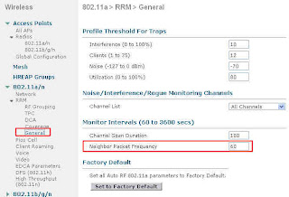
To change how often the RRM neighbour messages are sent, from your controller GUI, navigate to Wireless > 82.11a > RRM > General. Change the Neighbor Packet Frequency from 60 to the new interval you want to use. As you can guess, this is done on a per radio basis, do the same for 82.11b/g if you want to.


That's for the RRM neighbour message frequency. The RRM algorithm threshold cannot be changed from the GUI, but from the CLI. In your controller CLI, type:
(Cisco Controller) >config advanced 802.11a tx-power-control-threshold ?
Enter a value between (-50) and (-80)
And change the value to what is best. For example:
Cisco Controller) >config advanced 802.11a tx-power-control-threshold -79
You can of course use the "show advanced 82.11a tx-power-control-threshold" command to verify the current value. This changes the threshold for 82.11a, you need the same command for 82.11b/g if required.
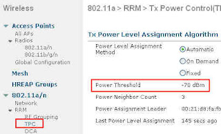
You can see the value of this threshold from the GUI, under Wireless > 82.11a > RRM TPC.
Before:


After!

Tuesday, July 28, 2009

OTAP - Over the Air Provisioning

You probably know OTAP, over the air provisioning of APs. When an access point boots, it can listen to the Air and receive information about controllers from the other APs. Do you want to know what does an OTAP message look like? How to read your controller IP address from a capture?
Watch here: http://www.youtube.com/watch?v=dZHiY_1p_d0
Imagine... you are in a lab, and the scenario says "your controller blahblah Management IP address was lost. Use the OTAP capture to find it. And basically if you can't find it, you can't get to it and configure it and this means the end of the journey for your lab..." you'd better be able to decipher OTAP messages, just in case!

Disclaimer: I DON'T know if this scenario is part of an actual lab or not! I just feel that at CCIE level, you are probably expected to understand OTAP well enough to know how to use it!
:-)

Monday, July 27, 2009

Hide that LED

In some environments the nice blinking LEDs on our controller based access points are not welcome: in some hospital environments they are said to create panic related reaction with some patients, in some school they are said to attract too much attention... well, you may be asked to make sure that this AP LEDs are disabled.
This is a controller CLI command. To disable the LEDs for an AP called AP5 (check your AP names with show ap summary):
(Cisco Controller) >config ap led-state disable AP5

To disable LEDs on all APs:
(Cisco Controller) >config ap led-state disable all.

Nice and easy. As you can guess, use the config ap led-state enable to revert the command.

Sunday, July 26, 2009

Wired Guest

You know the wireless guest feature, where users get a Web authentication page, enter username and password (or just enter their email address if it is a Pass Through config) to access the Internet.
The Wireless Business Unit has had the request for year to do the same for wired users... why? Well, juts because you always get that guy who does not have wireless, wants to plug somewhere just to check emails. Over the years, as the wireless guest access has become "the guest networks", we wireless guys are usually asked to take care of this "wired exception" along with the wireless standard guest users.
So now, the controller can also take care of these guys. It is easy to configure and very close to the wireless guest config. You can do it on one controller, or with 2 controllers, which is more interesting.
So imagine, you have a Switch, with a VLAN 50, which is the "Wired guest" VLAN. Whenever a wired guest wants access to the internet, plug the laptop to a port on that switch, in VLAN 50. This VLAN 50 guest to the trunk where you have your controller, called WLC1, waiting. WLC1 is your internal controller. It has quite a few WLANs and VLANs. It also receives the requests for wired (and wireless maybe) guest users, and sends them to the DMZ controller, DMZWLC.
So here is the process. Configuring Wired Guest Access is done is 5 steps:

1. Configure a dynamic interface (VLAN) for wired guest user access
2. Create a wired LAN for guest user access
3. Configure the Foreign controller (Main Office)
4. Configure the anchor controller (the DMZ controller)
5. Fine tune the guest LAN

1. On WLC1, create a dynamic interface VLAN50. In the interface configuration page, check the "Guest LAN" box. As soon as you check that box, fields such as IP address or gateway disappear. The only thing your WLC needs to know about this interface is that "there will be client traffic coming from VLAN 50. These clients are wired guests".

2. On a controller, an Interface is used when associated to a WLAN. The second step is therefore to create a WLAN on your Main Office controllers. Navigate to WLANs and click New.
In WLAN Type, choose Guest LAN.
In profile Name and WLAN SSID, enter a name that identifies what this WLAN is about. These names can be different, but cannot contain any space. The term WLAN is used, but this network profile has nothing to do with wireless.
The General tab offers 2 drop down list: one "Ingress" and one "Egress". Ingress is the VLAN users come from (VLAN 50), Egress is the VLAN you want to send them to.
For Ingress, choose VLAN50. Easy. For Egress, things are a little more interesting. If you had only one controller, you would create another dynamic interface, a "standard" one this time (i.e. NOT guest LAN), and you would send your wired users to this interface. In this case, we send them to the DMZ controller. So for the Egress interface, choose the Management Interface.
The Security mode for this Guest LAN "WLAN" is Web Auth, which is fine. Click Ok to validate.

3. From the WLAN list, click Mobility Anchor at the end of the Guest LAN line, and choose your DMZ controller. I am supposing here that both controllers know each others. If they do not know each other yet, go to Controller > Mobility Management > Mobility group, and add DMZWLC on WLC1, and similarly add WLC1 on DMZ. Both controllers do NOT need to be in the same mobility group (actually they'd better NOT be! Otherwise you would be breaking basic security rules here).

4. Your Main Office controller is ready. You now need to prepare your DMZ controller. Open a Web browser session to your DMZ controller and navigate to WLANs.
Create a new WLAN.
Just like on the Main Office controllers, in WLAN Type, choose Guest LAN.
In profile Name and WLAN SSID, enter a name that identifies what this WLAN is about. Use the same values as on the Main Office controller.
The Ingress interface here is None... It actually does not matter, as the traffic will be received through the EoIP tunnel, so this is why you do not need to specify any ingress interface.
The egress interface is the one on which the clients are supposed to be sent. Let's say that the DMZ VLAN is VLAN9. Create a standard dynamic interface for VLAN 9 on your DMZWLC, then choose VLAN 9 as the egress interface.
You need to configure the end of the Mobility Anchor tunnel. From the WLAN list, choose Mobility Anchor for Guest LAN. Send the traffic to the local controller, DMZWLC.
Both ends are now ready.

5. You can also fine tune the WLAN settings on both ends. Be careful, settings are to be exactly the same on both ends. For example, if you choose to click, in the WLAN Advanced tab, "Allow AAA override" on WLC1, you need to check the same box on DMZWLC. Any difference in settings in the WLAN on either side will make that the tunnel will break (DMZWLC will refuse the traffic, you can see that by running debug mobility).

Keep in mind that all values will actually be obtained from DMZWLC: IP addresses, VLAN values, etc. You configure the WLC1 side identically just for it to relay the request to the WLCDMZ...
Give it a try, and post here if it does not work.. :-)

Saturday, July 25, 2009

TPC vs DTPC vs World mode

Have you heard about TPC (Transmit Power Control), DTPC (Dynamic Transmit Power Control), and World Mode? They look the same, but do not actually do the same things... let's have a quick look at each of them:
- World Mode is probably the oldest one. It is a feature you can configure on the Autonomous (OIS) access points, and by which a client in World Mode receives its " radio parameters" from the access point. If you look a bit closer, you might read that "parameters" are actually channels and power levels. But don't take it wrong. "Channels" has an "s". It is not the channel on which the client should be! To hear the access point, the client has ANYWAY to be on the right channel. So what World Mode is about is "the list of allowed channels in this country" and "the power level ranges allowed in this country".
World mode is actually a Cisco implementation of the 802.11d protocol... but wait, why do we need that stuff? You are already on the right channel anyway! Well, for 2 reasons:
. Your client is going to scan for other APs offering the same SSID. You do not want your client to scan channel 13 if there is no AP on that channel because this channel is not allowed in your country... and you do not want your client to send a probe request on that channel if using it is forbidden...
. Your client power level might be too high for the country, thus creating issues for the other clients around it... what issues? Well, if you client is too powerful, it is going to associate at high speeds in areas where it should not even be able to associate, thus creating interference and hidden nodes issues for the other clients...
So the 802.11d protocol allows you to send the regulatory domain information to you client, which is going to adapt to them. Cool isn't it? The 802.11d protocol was integrated into the 802.11-2007 standard, thus allowing the possibility to send this information, without stating exactly how it could be sent. In a Cisco network, this can be contained in the Vendor Specific fields of the beacons. So where is that feature in the Autonomous APs? In the radio (802.11b / 802.11a) configuration page.
And in the Unified solution? Nowhere... what? did they forget it? Naahh, can't believe that... read further....

-TPC, Transmit Power Control, is actually a feature of 802.11h... You know 802.11h? This protocol that prevents your APs working outdoor on the 5 Ghz spectrum from interfering with airport radars... this protocol has two sides:
. DFS, Dynamic Frequency Selection, that makes that if your AP hears a radar blast on its current frequency, it sends a "changing channel" 802.11h message and jumps to another channel.
. TPC, Transmit Power Control, by which 2 devices initiating a communication in the 5 Ghz spectrum will negotiate so that their respective power level is as low as possible, just loud enough to hear each other (so that your noisy 50 mW access point does not disturb the poor 60 WATTS radar sitting next door!!).
Where do you configure TPC? Well, you don't really configure it. It is part of 802.11h, and your 802.11a device has to be compliant with it, and implements it automatically.

-DTPC, that's Dynamic Transmit Power Control, looks close to TPC hey? But this is Cisco stuff, not 802.11 something anymore. With DTPC, your Cisco access point transmits to your Cisco CCX compliant client information about which power level to use... looks somehow close to World mode, don't you think?
Yes, it's close... but do you know what caused the death of World mode and why you don't find this feature in a controller? Think about it... what does it exactly do? If (yes, "if"), you enable it, your clients will receive a pack of allowed channels and power levels from your AP. This information format is proprietary, so your client needs to be a CCX guy to understand it. And what does it do with that information? You don't know... your client may use it, if it is also configured for World mode. It may understand it but not use it, if it is CCX but not configured for World mode, it may not be able to use it if its drivers is not per-set for this regulatory domain, or it may not even understand it if the client CCX version is too old or if the client is not CCX... Whoa, what a result... so let's think about another approach.
If your client is CCX, you can actually do more: influence it. very often, your AP has a good 9 dBi patch antenna and your client has a poor rubber duck 2.2 dBi antenna. Your client hears the AP well, but the client signal is lost in the surrounding noise and your AP does not hear it well. Your client should increase its power level, but it does not know that the AP does not hear it well... all it knows is that it (the client) hears the AP well, and from this received signal deduces its own power level. If you client is CCX, the AP can tell to your client "I don't hear you well, increase your power to 20 mW", or "hey no need to shout! reduce your power to 5 mW, that will save your battery". In this information, the AP can communicate maximums ("increase your power again, but don't go beyond 50 mW"). Isn't that better than World mode? That's what DTPC is about. You can enable it in your controller from the Main radio menu (Wireless > 802.11a > Network, in the General field).
But what about the channels? Well, there is also another CCX feature by which an AP can tell a CCX client "don't scan, you are in my cell in a comfort zone, stay quiet and save battery". Or "your signal strength is decreasing, you should start scanning", and there are a lot of variation from there, from "scan channels 1,6,11" or "check channel 6, Ap aa:bb:cc:dd:ee:ff should be there"... isn't that even better?
Yes, but what about the non-CCX clients? Well, they would not have understood the World mode messages anyway, this is why CCX is cool...

Get a Pass

I took my CCIE Wireless lab a few weeks ago and got a pass.
After seeing many friends struggling for their studies and seeing quite a few people I highly respect for their technical level fail badly on their attempts, I decided to create this blog to exchange tips about the exam and how to prepare for it.
The CCIE Wireless exam is hard, but not infeasible if you know where you are going. A few tips:

1. Get yourself a CCNP wireless level. This does not mean actually pass the CCNP Wireless exams, but work the topics. There is no official resource (student guide or such) for the CCIE preparation, apart from bootcamps like the one from Fast Lane. Although you will definitely learn a lot from these bootcamps, you will only take full benefits of them if you come prepared with a level good enough level, so that you will only have to learn the few tips you miss and work your configuration speed. For the CCNP Wireless though, there are student guides and self prep books out there, so it's easy to go through them and make sure you master what they contain. Without breaking any NDA, if you look at the CCIE blueprint, you will see a lot of topics that look just likes the one listed in the CCNP Wireless courses...

2. Learn how to read minds... yes, you read that one right. You know, it is a CCIE exam, so they won't tell you "Hey, we would like you to configure this weird feature, you know the one that sits at the bottom of that page". They will more likely say "Configure your network to achieve this or that result". You will stop and think: "Okay, I know at least 3 ways to achieve what they want". Now, you can be sure that 2 of these 3 will be considered as the wrong answer... and you won't know until you get your "failed"....
How to figure out which solution they want? Well, there are a few ways:
- check if any of your possible answers breaks something else... it can be something they asked before, or something they will ask later on in the lab. Nothing magic here, and nothing you really care about during the initial "prepare" phase of your journey. Just be aware of the consequences of each configuration item. For example if they say "optimize your cell for voice" and if you think "hey, I should set the minimum speed to 24 Mbps", and if they say somewhere that 802.11b clients are in the same cell, you obviously can't remove any 802.11b speed... easy in an example, harder during the lab itself... so be aware of what side effect each configuration item has...
- check the exact phrasing... and that's where you get closer to mind reading. It could be things they say or things they don't say. An example: "most of your APs work fine, except one in that room that disconnects its clients because its power level is too weak. Solve the issue". You can easily guess that this is about setting the power level manually to a higher value. You can do it globally for all APs, and set them all to "1", or just for that AP. If most of the APs work fine, there is no way that they will accept the global solution, it has to be only for the problematic AP...
- Know what they think a CCIE should be... to you, it's a title, to them, it is a role, a position, a level of expertize that will guarantee that you will know the main problems of the real world and how to solve them. These problems obviously won't be newbie issues, but weird ones... so check the places where people talk about these issues... 2 main places I would recommend:
Cisco Forum : http://forums.cisco.com/eforum/servlet/NetProf?page=Wireless_-_Mobility_discussion
Cisco TAC Solution database for Wireless: http://www.ciscotaccc.com/wireless/home
Be sure you would be able to answer most questions and issues you see there. Not necessarily new questions about new issues you never heard about, but the ones already solved and documented, learn how they solved them...

3. Train on speed: during the lab, you don't have time to learn on how to configure stuff... you do have access to Cisco Documentation CD, but if you start looking in there, it's better be for a detail or a small item, otherwise you will run out of time. So during your training, configure stuff, learn to configure all variants, and know how to do it quick. If I tell you: "Configure ACM for Voice on 802.11a", your brain has to do: "ACM? That's Access Control management, in Wireless > 802.11a > Voice, but I first need to shut the 802.11a network". 2 clicks, done. You may not know about ACM yet (well, now you do!), but the main point is that, as soon as you do know about it, what it is and what it does, you have to know immediately where it is and what conditions exist to make it work (network has to be disabled first). Nothing magic here again, just pure practice, configure VoWLAN 2 times and you'll have done it 2 times!

4. Be curious. Do not limit yourself to the "Oh, I know how to configure a VoWLAN" (for example). Also look around. You'll notice small things... an example: oh, what is that "Web Radius Authentication" authentication feature in the Controller > General menu?... and BTW, why is it in the General menu if it is about RADIUS?... if you keep doing the same things and do not look around, you might be surprised when they ask you for a feature you never heard of... if you keep your eyes open, you will at elast have heard or read about what they ask...

One last thing... they can't really ask you magic things beyond what a controller or an Access Point can do. So it is a difficult exam, but if you learn your controller menus, know them all and know them well, do the same on an access point, you are close to the point where they can' t really surprise you anymore. All you need then is speed...

Good luck. It may be a long journey, but it is worth it...